Design a 4 bit synchronous up counter using t flip flop Counter synchronous flip flop lastly equation according 3 bit up down counter – 3 bit synchronous down counter – writflx design 4 bit synchronous counter
Circuit Design of a 4-bit Binary Counter Using D Flip-flops – VLSIFacts
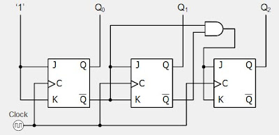
Digital system tutorial: 3-bit synchronous down counter with jk flip-flops 3 bit synchronous counter using d flip flop Counter bit synchronous down flip jk flop circuit flops digital count tutorial system
Design a 2 bit synchronous counter
4 bit synchronous counter using jk flip flop verilog codeCounter flip flop synchronous bit using circuit mod digital logic sequential Synchronous flopDesign 4 bit synchronous counter using ic 7476.
[最も共有された! √] t フリップフロッ プ 280004-tフリップフロップCounter bit synchronous binary counters ppt powerpoint presentation ff 4-bit synchronous binary counterSynchronous counter circuit diagram.

3 bit asynchronous up counter with circuit diagram and truth table
Counter synchronous flip flops enable count countersAsynchronous counter 4 bit synchronous counterSynchronous counter and the 4-bit synchronous counter.
Counter synchronous flip bit binary using flops parallel flipflop here4 bit ripple counter vhdl code for 8 Design a 3-bit synchronous binary counterDesign 3 bit synchronous up counter using jk ff.

Synchronous counters instrumentation tools
Elektrisch interview blick 4 bit asynchronous up down counter using jkSynchronous counter down bit counters instrumentationtools diagram circuit gate flop flip Circuit design of a 4-bit binary counter using d flip-flops – vlsifactsDesign a 3-bit gray code counter using jk flip flops.
Solved referring to the 4-bit synchronous up-counter with dDesign 4 bit synchronous up counter using t flip flop Erdnüsse claire ruhe 3 bit zähler drücken global ironieCircuit block diagram of counters.

Counter ripple flip flops synchronous negative vhdl carry triggered
Elektrisch interview blick 4 bit asynchronous up down counter using jkSynchronous binary Counter bit synchronousJk flip-flop counter circuit diagram.
Counter bit flip using binary flops circuit output q3 q1 q2 q0 collected would final4-bit synchronous “up” counter 3 bit synchronous counter truth table4-bit mod-12 synchronous counter using d flip-flop || sequential logic.

Working of 4 bit synchronous counter
Design a 4 bit synchronous up counter using t flip flopCounter circuit diagram 3 bit synchronous counter truth table.
.


